Premium
 Download
Edit
Download
Edit
Download the Resistors, Capacitors, and Inductors Facts & Worksheets
Click the button below to get instant access to these worksheets for use in the classroom or at a home.
Download This Worksheet
This download is exclusively for KidsKonnect Premium members!
To download this worksheet, click the button below to signup (it only takes a minute) and you'll be brought right back to this page to start the download!
Sign Me Up
Edit This Worksheet
Editing resources is available exclusively for KidsKonnect Premium members.
To edit this worksheet, click the button below to signup (it only takes a minute) and you'll be brought right back to this page to start editing!
Sign Up
Not ready to purchase a subscription? Click to download the free sample version Download sample
Download This Sample
This sample is exclusively for KidsKonnect members!
To download this worksheet, click the button below to signup for free (it only takes a minute) and you'll be brought right back to this page to start the download!
Sign Me Up
Table of Contents
The three basic elements in an electronic circuit consist of the resistor, capacitor, and inductor. Each of these elements interacts with electricity in a unique way, having its own standard symbols and units of measurement.
See the fact file below for more information on Resistors, Capacitors, and Inductors, or you can download our 30-page Resistors, Capacitors, and Inductors worksheet pack to utilize within the classroom or home environment.
Key Facts & Information
Introduction to Electricity Circuits
- Electricity is the energy attributed to the flow of electrons, moving from one atom to another in the same direction.
- When we flip a switch to use a gadget, a circuit facilitates the movement of electricity from a power source to what the circuit is powering.
- All existing gadgets are powered through electronic circuits, which use a combination of components, wires, and electricity to accomplish a specific function.
- Resistors, capacitors, and inductors are passive components of an electrical circuit, which means they do not need an external source of power such as electricity.
Basics of an Electronic Circuit
- A basic electronic circuit is comprised of three elements: a power source, components, and a wire connecting the components.
- The wire is a conductor as it has the property to carry electricity from place to place.
- Engineers simplify complex electronic circuits by drawing schematics, which utilize symbols to represent different components and illustrate how they all connect to each other.
- A printed circuit board is a medium used to connect electronic components to another to form a functioning circuit. Each layer has its own wires built onto it and components are soldered onto the surface of the board to make the electric connections.
- These layers can then transfer electricity to each other through the use of vias.
- There are two types of components in an electronic circuit, namely the passive and active components. The passive resides in the path of the actual circuit and does not need a connection to the power supply. Active components on the other hand inject power into the circuit by amplifying a signal from the supply. An example of this includes diodes, transistors, and integrated circuits.
Electric Current
- As mentioned, electricity is the flow of electrons from one place to another in the same direction. This is quantified in the form of an electric current.
- By convention, a current flows in the direction in which a positive charge would move. In the context of a circuit, it means the current would travel from the positive terminal to the negative terminal of a power supply.
- Current is measured as the flow of electric charge over time through a given point. This is equivalent to the definition of an ampere, or a coulomb over 1 second.
- The standard unit of measurement for ampere is A or amps, and the symbol for current itself is the letter “i.”
- There are two types of current used in everyday life: alternating current (AC) and direct current (DC). Batteries provide DC to power items and power lines use AC to transmit power over distances.
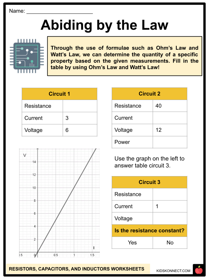
Ohm’s Law and Watt’s Law
- Ohm’s Law states that the strength of a current (I) is directly proportional to the voltage (V) and the resistance (R) of a circuit.
- Voltage and resistance are other forms of measurement relevant to electric circuits.
- Watt’s Law, on the other hand, states that the power (W) in a circuit is the product of the voltage (V) and the current (I).
- These laws are important as they help us determine the properties of a circuit based on the given values.
Resistance and Resistors
- A resistor is an electrical component that opposes or “resists” the flow of electric current in a circuit.
- Conductors such as metals have high electrical conductivity and therefore, little resistance. This allows electrons to move freely from one atom to the next.
- The resistance of the component is defined by Ohm’s Law as voltage divided by the current. This quantity is measured in Ohms with the symbol Ω.
- In schematic drawings of circuits, a resistor is symbolized by a zigzag line.
- Resistors may either be fixed or variable. Fixed-value resistors will always have the same resistance within the prescribed current and voltage limits. Variable resistors on the other hand have volume controls and dimmer switches that allow users to change the effective length or effective temperature of a resistor.
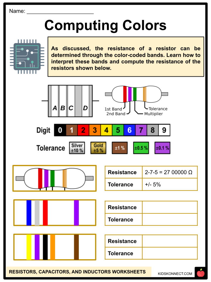
- Resistors come in a package that looks like a tube or a cylinder, with leads sticking out on each end.
- The color bands encircling the entire resistor package indicate the resistance, with each color representing a number.
- The placement of the bands indicates whether the value attributed to the color refers to resistance, tolerance or if it is a multiplier
- The resistance is read from a group of three bands then after a small gap to pertain to the single tolerance band.
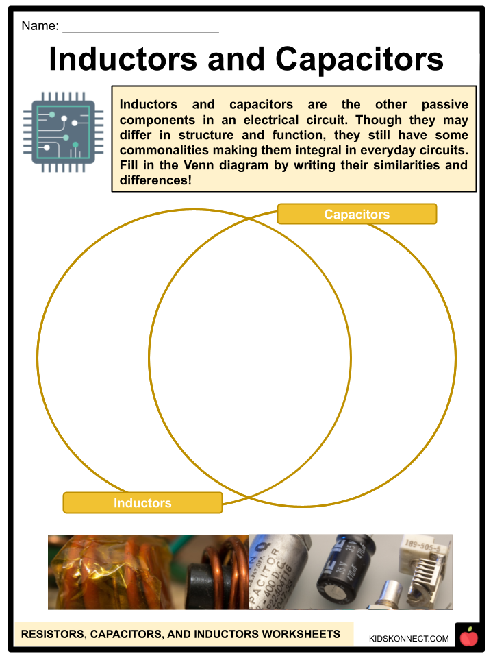
Capacitance and Capacitors
- Capacitors are similar to rechargeable batteries as they can store electrical energy. However, they have a lower capacity to store charge and quickly discharge.
- A capacitor is able to store energy by polarizing a dielectric or insulating material. When energy is added to the capacitors, the charges of the dielectric material separate, essentially storing the energy that was input.
- Capacitance is the amount of charge a capacitor can store per unit of voltage. This quantity is measured in farad with the symbol F.
- In schematic drawings of circuits, a capacitor is symbolized by two parallel lines, sometimes with one line curved.
- A simple capacitor consists of two flat conducting plates separated by a small gap. These capacitor plates are stacked in layers with a very small air gap to maximize efficiency. Insulating materials which partially block the electric field are placed within the air gap to allow the capacitor to store more charge without shorting out.
- Capacitors are often used in gadgets with oscillating electric signals such as radios and audio equipment. One plate will be charged by an oscillating signal while the other plate discharges, allowing these gadgets to filter selected frequencies within a specified range.
- Generally, capacitors allow higher frequencies to pass through and block lower frequencies such as DC signals.
Inductance and Inductors
- Inductors can also store energy like capacitors but through a different mechanism.
- Energy is stored in inductors through a magnetic field. Current-carrying conductors can generate a magnetic field, and this magnetic field can be intensified when the wire is coiled.
- Inductance is the ability of the component to generate electromotive force due to a change in current flow.
- Inductance is measured in Henrys with the symbol “L.”
- An inductor consists of a simple coil wire with an electric current running through it.
- Inductance has no effect when the current coursing through the circuit is constant such as in a DC circuit. There will only be an effect when the current is changing, such as in an AC circuit.
- Thus, the use of this component is generally the opposite of a capacitor: an inductor allows lower frequency oscillations to pass and blocks higher frequencies such as AC signals.
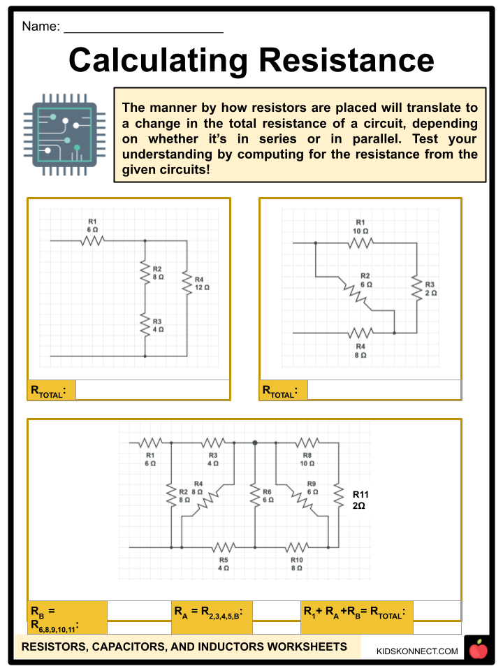
Resistors in Series
- Resistors are in a series when they are connected end-to-end in a circuit. Determining the total resistance of resistors in a series is straightforward as you would have to add up the value of each resistor.
Resistors in Parallel
- On the other hand, parallel resistors are resistors connected across from each other in an electric circuit.
- The calculation of the total resistance of these resistors in this orientation is not the same as that of a series, as some of the current will travel through R1, R2, and R3.
- In order to calculate the total resistance, the following formula should be used: 1/Rtotal = 1/R1 + 1/R2 + 1/Rn
Resistors in Series and Parallel
- The series and parallel configuration confer specific properties to resistors.
- Resistors in series have the same current and resistors in parallel have the same voltage.
- To solve circuits with both parallel and series resistors, break them down into smaller sections.
- As a rule of thumb, do the sections with only series resistors.
- RA = 1 Ω + 5 Ω = 6 Ω
- RC = 3 Ω + 7 Ω = 10 Ω
- Next, solve the parallel resistors.
- RAB = 1/(1/6 + 1/12) = 1/(3/12) = 4 Ω
- Replace the sections with the equivalent resistors. Once done, solve the simplified circuit.
- RCD = 10 + 11 = 21 Ω
- RTotal = 1/(1/4 + 1/21) = 1/(25/84) = 3.36 Ω
Resistors, Capacitors, and Inductors Worksheets
This is a fantastic bundle that includes everything you need to know about Resistors, Capacitors, and Inductors across 30 in-depth pages. These are ready-to-use worksheets that are perfect for teaching kids about Resistors, Capacitors, and Inductors, which are the three basic elements in an electronic circuit.
Complete List of Included Worksheets
Below is a list of all the worksheets included in this document.
- Resistors, Capacitors, and Inductors
- Which is Which?
- Word Hunt
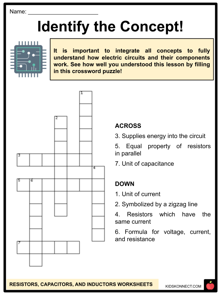
- Identify the Concept!
- Inductors and Capacitors
- Computing Colors
- Abiding by the Law
- Calculating Resistance
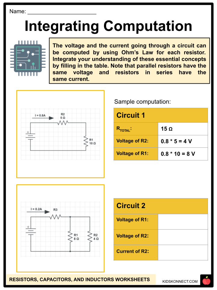
- Integrating Computation
- Drawing Conclusions
- Creating Circuits
Link/cite this page
If you reference any of the content on this page on your own website, please use the code below to cite this page as the original source.
Link will appear as Resistors, Capacitors, and Inductors Facts & Worksheets: https://kidskonnect.com - KidsKonnect, October 6, 2022
Use With Any Curriculum
These worksheets have been specifically designed for use with any international curriculum. You can use these worksheets as-is, or edit them using Google Slides to make them more specific to your own student ability levels and curriculum standards.