Premium  Download Edit
Download the Electric Circuits Facts & Worksheets
Click the button below to get instant access to these worksheets for use in the classroom or at a home.
Download This Worksheet
This download is exclusively for KidsKonnect Premium members!
To download this worksheet, click the button below to signup (it only takes a minute) and you'll be brought right back to this page to start the download!
Sign Me Up
Edit This Worksheet
Editing resources is available exclusively for KidsKonnect Premium members.
To edit this worksheet, click the button below to signup (it only takes a minute) and you'll be brought right back to this page to start editing!
Sign Up
Not ready to purchase a subscription? Click to download the free sample version Download sample
Download This Sample
This sample is exclusively for KidsKonnect members!
To download this worksheet, click the button below to signup for free (it only takes a minute) and you'll be brought right back to this page to start the download!
Sign Me Up
Table of Contents
An electronic circuit comprises device/s connected by conductive wires, allowing electric current to flow through its closed path, powering the device by the electrons carrying the charge in rotation. An example of an electronic circuit requires lighting a bulb by connecting its wires to a battery.
See the fact file below for more information on Electric Circuits, or you can download our 32-page Electric Circuits worksheet pack to utilise within the classroom or home environment.
Key Facts & Information
INTRODUCTION TO ELECTRICAL CIRCUITS
- An electron is a negatively charged subatomic particle found in all atoms and primarily produces electricity.
- An electric circuit is made up of the following parts:
- An internal circuit is where the electrons flow continuously, such as in batteries and electrochemical cells.
- An external circuit is where the electrons flow outside the electrochemical cell through the wires and connected devices.
- For a circuit to be considered functional, it has to satisfy the following conditions:
- A circuit must be closed, meaning no gaps would show in the connection of wires;
- The wires should be connected from the positive terminal to the negative terminal of the electrochemical cell for the opposite charges to flow and;
- The materials used in the circuit should be good conductors, allowing a continuous flow of the conduction electrons.
- It is also possible for a circuit to be functional even if it is an open circuit, provided a switch is in place to close the circuit when needed.
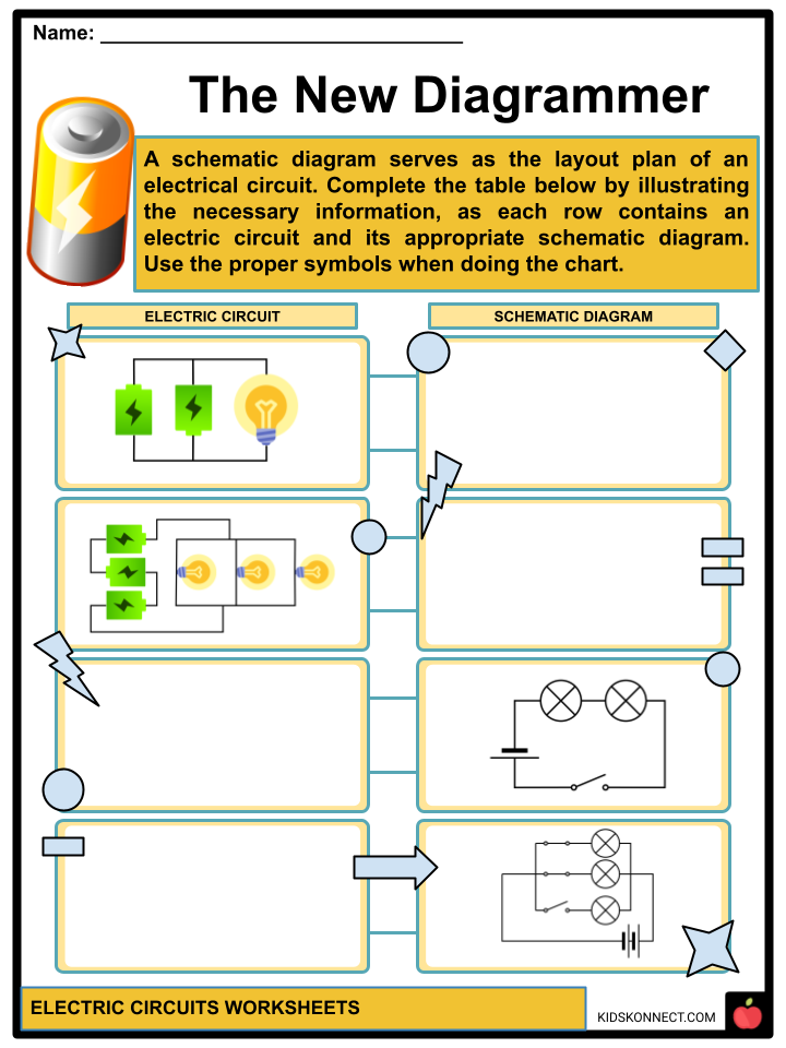
- In creating an electric circuit, it is most common to illustrate the layout before construction in the real world. This can be done through schematic diagrams, as symbols and lines represent the components of an electric circuit.
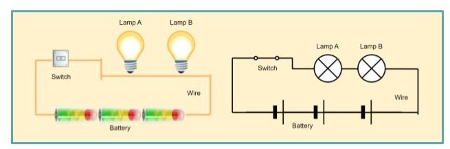
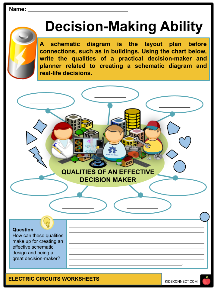
- A schematic diagram serves as the layout plan of an electrical circuit commonly used before connections are made, such as in buildings, infrastructures, and interior settings.
- An example of the schematic diagram above shows the relationship between the electricity flowing through the lamps fueled by the battery and the electrochemical cell, which can be powered on and off through a switch. When the switch is turned on, it will close the circuit, lighting the lamps in the process.
ELECTRIC CURRENTS AND ELECTRICAL CIRCUITS
- Voltage drop refers to the decrease in the electric potential as electric energy is converted into other forms of energy to power component/s that is/are connected to a given circuit.
- When there is an excess voltage drop in a circuit, it affects the efficiency of the components.
- Equivalent resistance refers to the resistance that a single resistor would need to equal the overall effect of all the resistors present in a given circuit.
- There are mainly two types of circuits: Series circuits and parallel circuits.
TYPES OF ELECTRICAL CIRCUITS: SERIES CIRCUIT
- Series circuits require the use of two or more components to be connected to one single path, allowing the same amount of current to flow through each of the components.
- However, because the same amount of current flows through all the components, when one of the components stops or fails to work, all the components stop working as well.
- An application of series circuits can be seen in Christmas or decorative string lights. When one bulb does not work, all lights in the connection do not light up.
- Components are connected to form one single path.
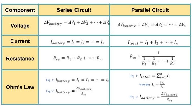
- The total voltage of a given source in a series circuit is the sum of the individual voltage drops. The current of each component or device in a series circuit is the same as the electric current passing through a single path.
- The total resistance of a series circuit is equal to the sum of the individual resistances. Therefore, the components connected in a series circuit vary directly to its overall resistance.
TYPES OF ELECTRICAL CIRCUITS: PARALLEL CIRCUITS
- Parallel circuits involve an independent branch for each component connected to a node. This allows other devices to continue working when one of the devices stops working.
- The node refers to the connection point of all branches to the same source.
- When too many branches are connected in this type of circuit, it can lead to an unsafe total amount of current, overloading and causing a fire hazard.
- An application of parallel circuits can be seen in modern housing wherein lights and appliances connected are unaffected when one of them fails to work correctly.
- The total voltage of a given source in a parallel circuit is equal across all components or devices connected. The current of each component or device in a parallel circuit is the sum of currents in the parallel branches.
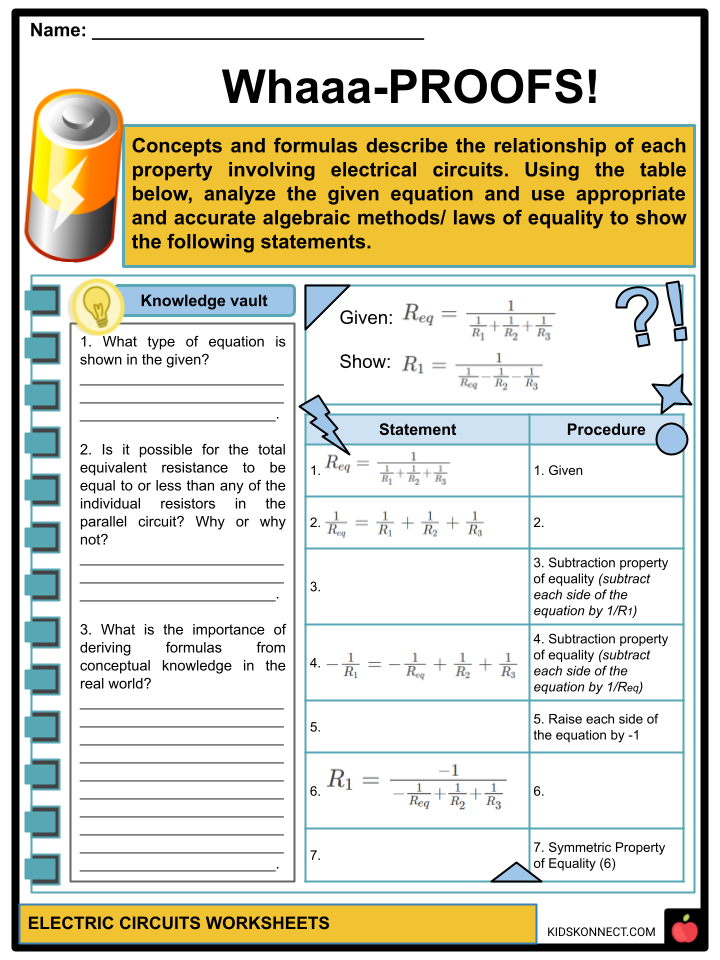
- The total resistance of a parallel circuit is inversely proportional to the sum of the inverse of all the resistance of different branches.
- This means that the number of parallel branches is inversely proportional to the resistance in a parallel connection.
OHM’S LAW
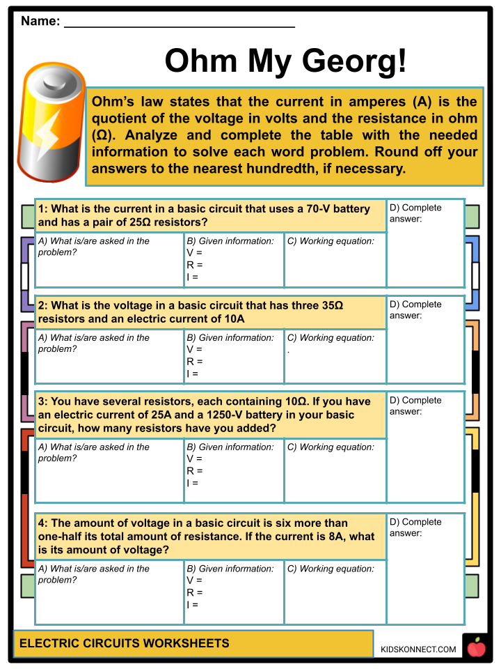
- When discussing electric circuits, Ohm’s law is a formula stating that the voltage across a conductor is directly proportional to the current flowing through it.
- This shows that the current in amperes (A) is the quotient of the voltage in volts and the resistance in ohms (Ω). It was published in 1827 by Georg Ohm.
- Since the current is directly proportional to the voltage and inversely proportional to the resistance, the voltage supplies the current’s energy, and the resistance regulates the strength of the current.
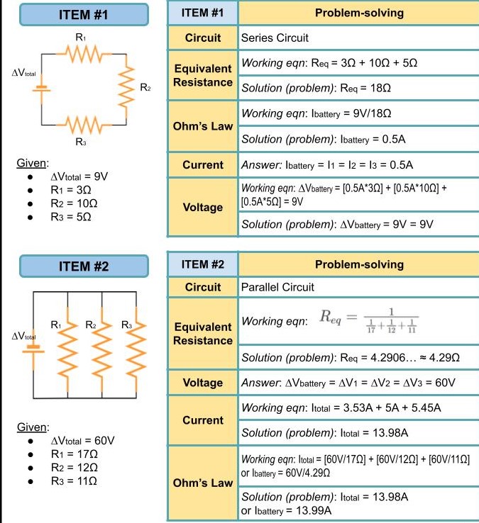
EQUATIONS RELATED TO ELECTRICAL CIRCUITS
ELECTRICAL HAZARDS
- A significant increase in the use of electronic devices and technology becomes directly linked to several hazards that could happen frequently and in different places.
- The level of body resistance varies inversely with the injury that can occur when exposed to a particular hazard.
- A high body resistance will lessen the injury incurred, while a low body resistance increases the damage.
- The human body is a good conductor of electricity and can withstand less than ten milliamperes (mA) before it can cause powerful muscle contractions that make it unable to control its hands and arm muscles.
- Touching devices with wet hands is dangerous as the electricity may pass through the body, causing an electric shock.
- Overloading commonly happens in parallel circuits when too many devices are connected to the same circuit, potentially causing fires.
- A short circuit can happen in parallel and series circuits when it acquires too much current, causing high temperatures that can lead to fire, damage, and explosions that will blow up the power source.
- A short circuit happens when a low-resistance connection between two conductors supplies electrical energy. This can also occur in a poor connection of wires, and overloading.
- Downed power lines are very dangerous, especially when you come in contact with a live wire as it touches the ground. This can send a harmful (even deadly) amount of electricity through your body.
ELECTRICAL SAFETY
- There are several safety devices and precautions that can be taken to maximize safety in using electrical appliances.
- Safety fuses are connected along a supply line which includes a fuse ribbon inside, ready to blow out if the current in a circuit reaches unsafe levels. Once blown out, it must be replaced with a new safety fuse after identifying the problem in the circuit itself.
- Circuit breakers are used in modern interiors to protect electric lines. It functions similarly to a safety fuse by interrupting the current flow of the circuit when the current reaches unsafe levels. Once it detects a problem, it does not get destroyed and the circuit can be switched back on once the problem is solved.
- Earthing or Grounding System prevents electric shocks and the damage it could do to your body by connecting a wire to the ground, creating a path of least resistance. This is commonly found in power plugs and device chargers with a third prong in the plug connected to the grounding system.
- Double insulation is used when wires are covered in plastic before being placed in an outer casing so that they don’t create a short circuit once they touch each other.
- Take off your jewelry when around electricity as metals are a good conductor of electricity, making your body’s resistance low.
- Be aware of overhead wires and wires underground. Be sure to maintain a safe distance from overhead wires, especially when they are live. Make sure to check for any wires underground.
- Avoid planting trees near power lines. The moisture between the tree and you will be a great conductor of electricity. When attempting to trim the trees when they have grown into the power lines, call the electricians or the electricity department.
- Do not touch downed wires. Call the electricity department to address the problem and stay 10 meters away from the wires.
- Do not touch a component in a circuit that has power.
- Do not do electrical work when you’re not a trained or certified electrician.
- Take regular checks with your tools used in electrical circuits.
- When somebody comes in contact with a live electrical current and suffers an electric shock, DO NOT touch the person, as you may also get an electric shock in the process.
- You can turn off the appliance or get the person away by using non-conductive objects when turning the power of the device off is not a viable option.
- When a power line falls on a car, stay inside the car unless it will catch fire or cause an explosion.
- Remember to contact emergency services when necessary and remember basic first aid procedures.
Electric Circuits Worksheets
This is a fantastic bundle that includes everything you need to know about Electric Circuits across 32 in-depth pages. These ready-to-use worksheets are perfect for teaching students about Electric Circuits. An electronic circuit comprises device/s connected by conductive wires, allowing electric current to flow through its closed path, powering the device by the electrons carrying the charge in rotation.
Complete List Of Included Worksheets
- Electric Circuit Facts
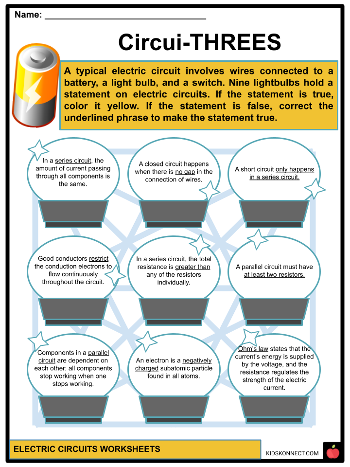
- Circui-THREES
- The New Diagrammer
- Ohm My Georg!
- Electric Boogaloo I
- Electric Boogaloo II
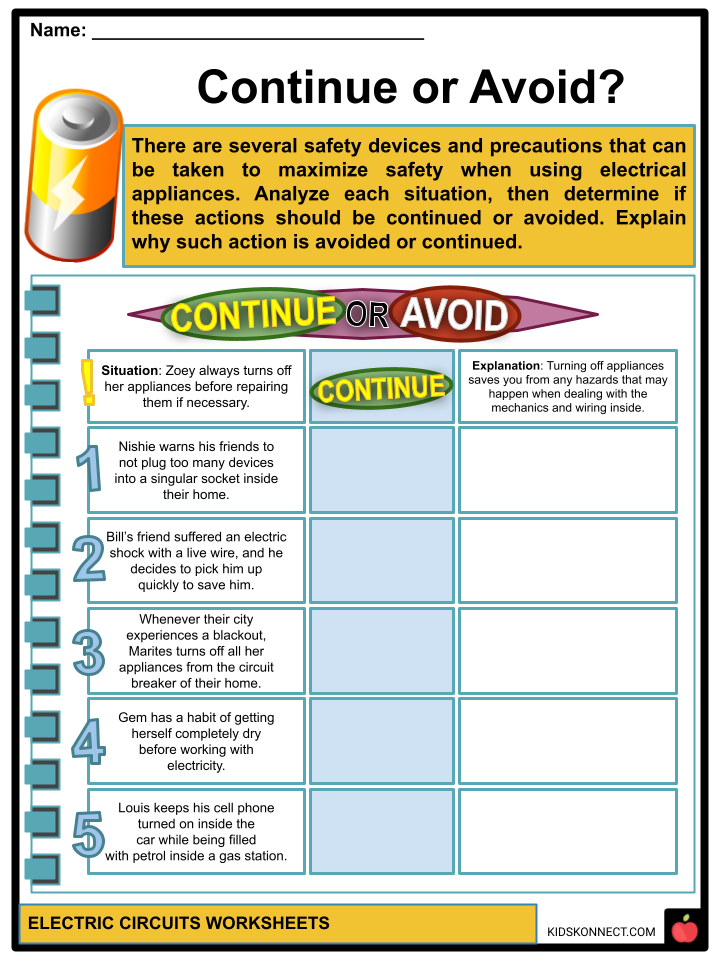
- Continue or Avoid?
- Decision-Making Ability
- Georg-BoutToBe-Found
- Whaaa-PROOFS!
- Merchandise
Frequently Asked Questions
What is an electric circuit?
An electric circuit is a closed loop or pathway through which electric current can flow. It consists of various components such as resistors, capacitors, inductors, and sources of electrical energy (like batteries or generators). Circuits allow the controlled movement of electrons, enabling the transfer of electric energy to perform tasks like powering devices and generating light.
What is the difference between series and parallel circuits?
Series and parallel circuits are two common ways of connecting components within an electric circuit.
- Series Circuit: In a series circuit, components are connected end-to-end, forming a single pathway for the current. The same current flows through all components, and the voltage is divided among them. If one component fails or is disconnected, the entire circuit is interrupted.
- Parallel Circuit: In a parallel circuit, components are connected across common points, creating multiple paths for the current. Each component gets the full voltage, but the current divides among them. If one component fails, the others can continue to function.
What is Ohm’s Law?
Ohm’s Law is a fundamental principle in electrical engineering that relates the current (I), voltage (V), and resistance (R) in an electric circuit. It can be expressed by the equation:
V = I * R
Where:
- V is the voltage across a component in volts (V).
- I is the current flowing through the component in amperes (A).
- R is the resistance of the component in ohms (Ω).
Ohm’s Law helps determine how voltage, current, and resistance are interconnected in a circuit.
What is a resistor?
A resistor is a passive electrical component that restricts the flow of electric current. It is typically used to control the amount of current flowing through a circuit or to create voltage drops. Resistors are measured in ohms (Ω) and are represented by a color code that indicates their resistance value. They come in various shapes and sizes and are often used in combination with other components to achieve specific electrical behaviors in circuits.
What is a capacitor?
A capacitor is an electrical component that stores and releases electrical energy in a circuit. It consists of two conductive plates separated by an insulating material called a dielectric. When a voltage is applied across the plates, they accumulate opposite charges, creating an electric field between them. Capacitors are used for various purposes, such as smoothing out voltage fluctuations, storing energy for quick release, and blocking direct current while allowing alternating current to pass. They are measured in farads (F).
Link/cite this page
If you reference any of the content on this page on your own website, please use the code below to cite this page as the original source.
Link will appear as Electric Circuits Facts & Worksheets: https://kidskonnect.com - KidsKonnect, August 31, 2023
Use With Any Curriculum
These worksheets have been specifically designed for use with any international curriculum. You can use these worksheets as-is, or edit them using Google Slides to make them more specific to your own student ability levels and curriculum standards.


